Atmega328p-Bluetooth-programming
From
goal
uploading code over bluetooth to your avr microcontroller,
for when you can't just reach with a cable.
here is a demo:
hardware
The board is based on Arduino Standalone
I used this bluetooth module: (which I found here: Bluetooth module)

BOM for schematic:
Part Value   Device  Package Description
BT_H H1      FE07-1  FE07    FEMALE HEADER
C1   100nf   C2.5/2  C2.5-2  CAPACITOR
C2   100nf   C2.5/2  C2.5-2  CAPACITOR
C3   100nf   C2.5/2  C2.5-2  CAPACITOR
C4   100nf   C2.5/2  C2.5-2  CAPACITOR
IC1  MEGA8-P MEGA8-P DIL28-3 MICROCONTROLLER    (or in my case atmega328p-pu)
JP1  BT_KEY  JP1E    JP1     JUMPER
Q1   16Mhz   XTAL/S  QS      CRYSTAL
R3   1K      R0204/7 0204/7  RESISTOR, European symbol
SV2  H2      FE06-1  FE06    FEMALE HEADER
SV3  H3      MA03-1  MA03-1  PIN HEADER
SV4  H4      FE06-1  FE06    FEMALE HEADER
SV5  H5      MA03-1  MA03-1  PIN HEADER
schematic
Here is a working schematic I made, the main IC is a atmega8,
But I use a atmega328.
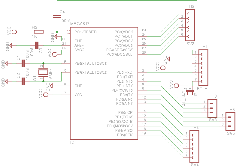
Header1 (BT_H) is where you connect the bluetooth module.
in my case a bluetooth module that already had pin header.
mine looks like:
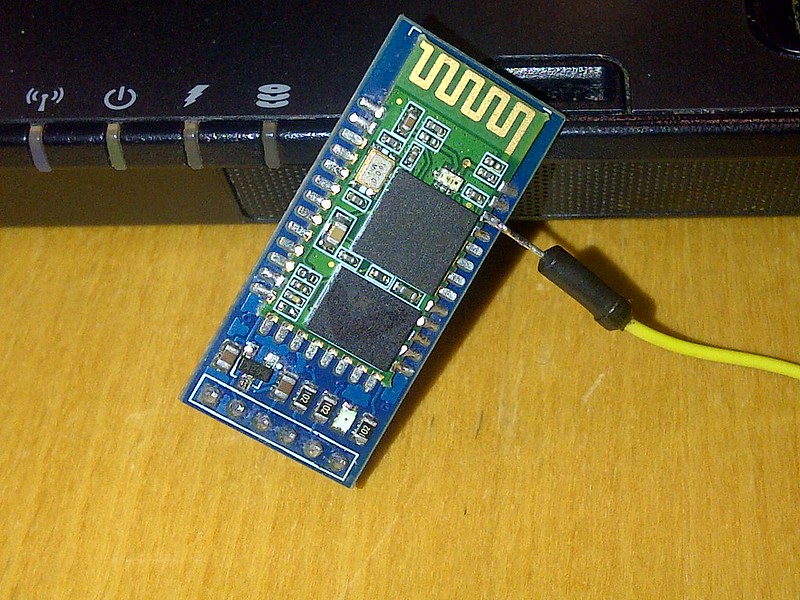
the yellow wire is my reset.
this is explained in setting up bluetooth.
The yellow wire is connected to pin1 of Header1 as this is the reset pin.
setting up bluetooth
For this part we are going to do a little trick,
What normaly happens when you program a chip, is the reset is pulled,
which then causes the chip to go in programming mode
Arduino for example does this with the dtr/cts pin (they are not the same, but are connected to the reset in arduino schematic)
so that the board "knows" that program data is on it's way.
The bluetooth module I use has two pins that can be setup to toggle, when you connect to it via bluetooth
for that we need to setup the bluetooth module so it knows what it should do.
besides that we need to set the communication speed (115200 baud) and parity.
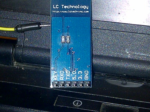
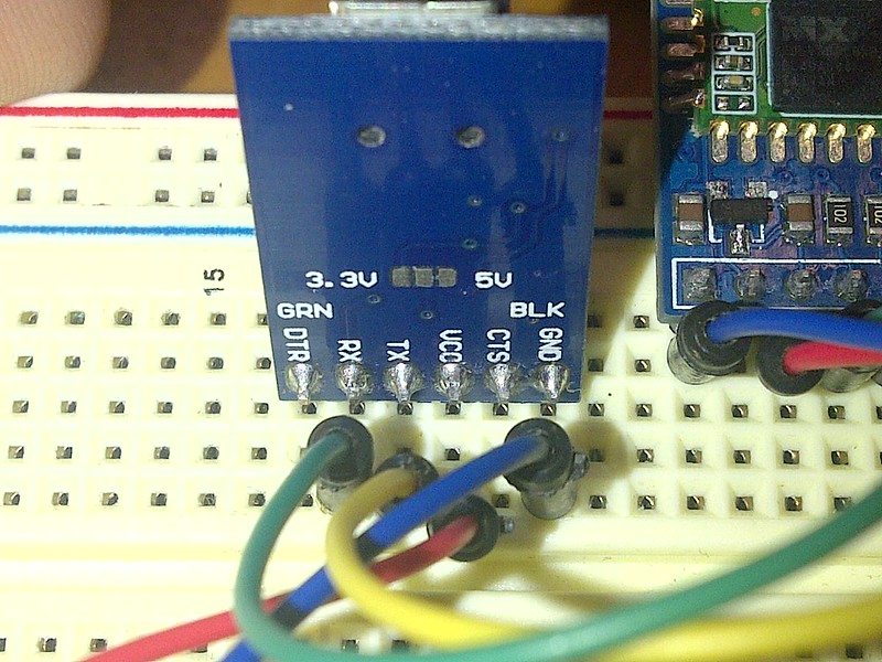
I did this by connecting to the bluetooth module through a usb-serial device,
the key pin has to be pulled high, for the bluetooth module to go in command mode.
then I connected the bluetooth module to the usb-serial.
Connect the grounds of the usb-serial and bluetooth together.
then Connect the RXD from the usb-serial to the TXD of the bluetooth module.
and connect the TXD from the usb-serial to the RXD of the bluetooth module.
and if your usb-serial has a 5v line, connect that to the 5.0v on the bluetooth module.
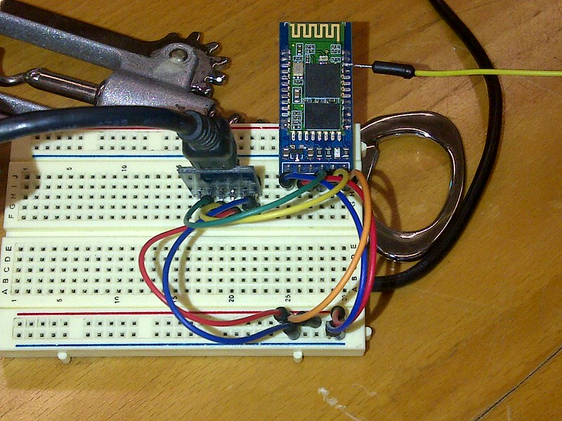
this is the module, the blue wire is ground, red is 5.0v, green is TXD, yellow is RXD, and orange is KEY.
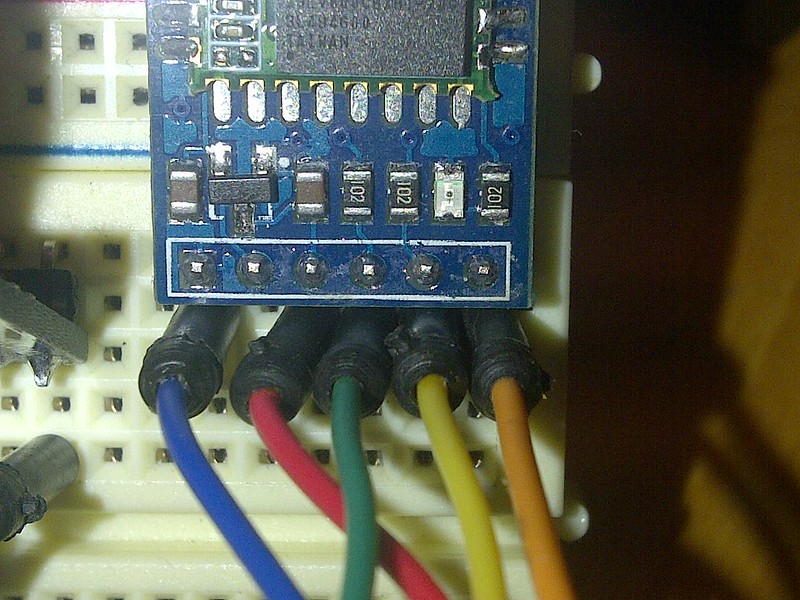
I Connected the orange wire to 5v to put the bluetooth module in programming mode
This is how I then connected the Serial module: (notice) green TXD is connected to RXD on the serial.
this is what it in the end looks like:
So when everything is working properly, I opened a serial terminal (cutecom is a good one),
The bluetooth module by default comunicates at 38400 baud, if it is unconfigured.
and If you then send the following "AT\r\n" it should respond with "OK", it's important that we send the \r\n, or
else the bluetooth module won't know it recieved a command.
then we configure with the following:
AT
AT+RESET
AT+ORGL
AT+ROLE=0
AT+POLAR=1,0
AT+UART=115200,0,0
AT+INIT
AT+INQ
RESET resets the module,
ORGL is a factory reset.
with ROLE we set it to be a slave
with POLAR, we set the pin that we use for the reset, to go from low to high when connecting over bleutooth
UART sets the baudrate to 115200, and 1 stop bit, and no parity.
INIT and INQ makes the module listen for incoming connections.
now the module is fully setup.
you notice that we set pin configuration with POLAR, that is because pin 32 (the pin I solderd a wire to) toggles when we connect on bluetooth, and resets the atmega.
So now we are done with configuring, you want to put the bluetooth module into normal operation mode.
just simply disconnect the KEY pin from the 5v line, and cycle the power, the module should be reachable, and you
should be able to pair, the standard pin is 1234
Programming under Linux
First we have to figure out what the mac of our bluetooth device is.
under linux we can the hcitool to do that.
In my case I called my bluetooth device "program me 1234"
so when we use hcitool to scan for devices we do (in a terminal):
:$ hcitool scan
which gives output like:
	Scanning ...
	00:13:04:01:10:05	program me 1234
now we have our mac: 00:13:04:01:10:05
we can bind this address to our serial port with rfcomm like so:
:$ rfcomm bind 0 00:13:04:01:10:05 1
this will bind the device to /dev/rfcomm0
everytime we connect with avrdude for example, it automaticly triggers
a reset, so we can upload our code.
now we can look if the chip is connected with:
:$ avrdude -c arduino -p m328p -P /dev/rfcomm0
yes the chip has a arduino bootloader, that is why -c arduino
with avrdude we connect to the chip to see if it is connected properly
-p m328p meens we select the atmega328p chip. -P select the port our chip is connected on. (rfcomm0)
the command shows this as output:
	avrdude: AVR device initialized and ready to accept instructions

	Reading | ################################################## | 100% 0.04s

	avrdude: Device signature = 0x1e950f

	avrdude: safemode: Fuses OK

	avrdude done.  Thank you.
the logical thing to do next is to upload code,
there are a few options that you can to compile.
you can compile it on your own with avr-gcc or avr-g++
or you can compile it through the arduino ide if you made arduino code.
if you made your .hex with the arduino ide you need to know where to look
if you look in the /tmp/ folder, you see a few folders.
like:
:/tmp$ ls
build2878010465348774496.tmp    hsperfdata_robert
console3268551129024207709.tmp  untitled3650258705103207149.tmp
geany_socket.d197a52e
and your code is in a folder that starts with build,
in this case build2878010465348774496.tmp
inside there wil be your code, there is alot of other stuff,
but what your looking for is the file that ends in .hex
this is inside mine:
	:/tmp/build2878010465348774496.tmp$ ls
	CDC.cpp.d             Print.cpp.o            WInterrupts.c.o
	CDC.cpp.o             realloc.c.d            wiring_analog.c.d
	core.a                realloc.c.o            wiring_analog.c.o
	HardwareSerial.cpp.d  sketch_feb04a.cpp      wiring.c.d
	HardwareSerial.cpp.o  sketch_feb04a.cpp.d    wiring.c.o
	HID.cpp.d             sketch_feb04a.cpp.eep  wiring_digital.c.d
	HID.cpp.o             sketch_feb04a.cpp.elf  wiring_digital.c.o
	IPAddress.cpp.d       sketch_feb04a.cpp.hex  wiring_pulse.c.d
	IPAddress.cpp.o       sketch_feb04a.cpp.o    wiring_pulse.c.o
	main.cpp.d            Stream.cpp.d           wiring_shift.c.d
	main.cpp.o            Stream.cpp.o           wiring_shift.c.o
	malloc.c.d            Tone.cpp.d             WMath.cpp.d
	malloc.c.o            Tone.cpp.o             WMath.cpp.o
	new.cpp.d             USBCore.cpp.d          WString.cpp.d
	new.cpp.o             USBCore.cpp.o          WString.cpp.o
	Print.cpp.d           WInterrupts.c.d
in this case its this file: sketch_feb04a.cpp.hex
quick note though the .hex wil only show if you compile in the ide first.
now to upload your code, if your in the same folder as the .hex you would do:
avrdude -c arduino -p m328p -P /dev/rfcomm0 -U flash:w:sketch_feb04a.cpp.hex
this would create this output indicating it is a succes!:
	avrdude: AVR device initialized and ready to accept instructions

	Reading | ################################################## | 100% 0.04s

	avrdude: Device signature = 0x1e950f
	avrdude: NOTE: FLASH memory has been specified, an erase cycle will be performed
			 To disable this feature, specify the -D option.
	avrdude: erasing chip
	avrdude: reading input file "sketch_feb04a.cpp.hex"
	avrdude: input file sketch_feb04a.cpp.hex auto detected as Intel Hex
	avrdude: writing flash (866 bytes):

	Writing | ################################################## | 100% 0.61s

	avrdude: 866 bytes of flash written
	avrdude: verifying flash memory against sketch_feb04a.cpp.hex:
	avrdude: load data flash data from input file sketch_feb04a.cpp.hex:
	avrdude: input file sketch_feb04a.cpp.hex auto detected as Intel Hex
	avrdude: input file sketch_feb04a.cpp.hex contains 866 bytes
	avrdude: reading on-chip flash data:

	Reading | ################################################## | 100% 0.61s

	avrdude: verifying ...
	avrdude: 866 bytes of flash verified

	avrdude: safemode: Fuses OK

	avrdude done.  Thank you.
Reference
Arduino Bluetooth
Lets make Robots, Program Arduino over Bluetooth
Bluetooth module
