Difference between revisions of "Arduino KY-032 Obstacle avoidance sensor module"
From
| (9 intermediate revisions by 2 users not shown) | |||
| Line 1: | Line 1: | ||
| − | |||
| − | |||
[[File:Arduino KY-032 Obstacle avoidance sensor module.PNG|400px]] | [[File:Arduino KY-032 Obstacle avoidance sensor module.PNG|400px]] | ||
| − | + | Buy this [http://www.dx.com/p/arduno-37-in-1-sensor-module-kit-black-142834?Utm_rid=92935131&Utm_source=affiliate sensors] or [http://www.dx.com/p/arduno-37-in-1-sensor-module-kit-black-142834?Utm_rid=92935131&Utm_source=affiliate kit]. | |
{{#widget:AdSense | {{#widget:AdSense | ||
| Line 11: | Line 9: | ||
=Infrared obstacle avoidance sensors= | =Infrared obstacle avoidance sensors= | ||
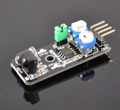
| − | Infrared obstacle avoidance sensor is designed | + | This Infrared Obstacle Avoidance Sensor returns a signal when it detects an object in range. The range of the sensor is around 2-40 cm is distance. It operates at 3.5 to 5 volts at around 20 milliamps. The Obstacle Avoidance Sensors usually come in two types - with 3 and 4 pins. The 3 pin version does not have the ability to be enabled/disabled. The 4 pin version has optional Enable pin. Infrared obstacle avoidance sensor is designed to detect obstacles or the difference in reflective services. One application is to help a wheeled robot avoid obstacles with a sensor to react to adjustable distance settings. This device has an infrared transmitter and receiver, that forms the sensor pair. The transmitter LED emits a certain frequency of infrared, which the receiver LED will detect. The receiving LED will detect some of the signal back and will trigger the digital on/off “signal” pin when a specific threshold “distance” has been detected. Most boards will have 2 potentiometers, one of which is to adjust how sensitive the sensor is. You can use it to adjust the distance from the object at which the sensor detects it. Typically, the other potentiometer, which changes the transmitter IR frequency is not adjusted. |
| − | |||
=Specifications= | =Specifications= | ||
* Working voltage: DC 3.3V-5V | * Working voltage: DC 3.3V-5V | ||
| Line 53: | Line 50: | ||
</syntaxhighlight> | </syntaxhighlight> | ||
| + | |||
| + | =Links and Resources= | ||
| + | Data Sheet: Proximity Sensor https://www.sparkfun.com/datasheets/Sensors/Infrared/gp2y0a02yk_e.pdf | ||
| + | |||
| + | AdaFruit: IR Distance Sensor https://www.adafruit.com/product/1568 | ||
| + | |||
| + | Tutorial: Infrared Obstacle Avoidance Sensor - https://www.instructables.com/id/Arduino-Nano-Infrared-Obstacle-Avoidance-Sensor-Wi/ | ||
| + | |||
| + | YouTube: Using basic Infrared sensor for distance measurement - https://www.youtube.com/watch?v=iAWslxNC7e4 | ||
| + | |||
| + | YouTube: IR Proximity Sensor / Obstacle Detector circuit on Breadboard <-- individual components on a bread board - https://www.youtube.com/watch?v=qEMtCKfZOHw | ||
Latest revision as of 20:27, 13 July 2019
Contents
Infrared obstacle avoidance sensors
This Infrared Obstacle Avoidance Sensor returns a signal when it detects an object in range. The range of the sensor is around 2-40 cm is distance. It operates at 3.5 to 5 volts at around 20 milliamps. The Obstacle Avoidance Sensors usually come in two types - with 3 and 4 pins. The 3 pin version does not have the ability to be enabled/disabled. The 4 pin version has optional Enable pin. Infrared obstacle avoidance sensor is designed to detect obstacles or the difference in reflective services. One application is to help a wheeled robot avoid obstacles with a sensor to react to adjustable distance settings. This device has an infrared transmitter and receiver, that forms the sensor pair. The transmitter LED emits a certain frequency of infrared, which the receiver LED will detect. The receiving LED will detect some of the signal back and will trigger the digital on/off “signal” pin when a specific threshold “distance” has been detected. Most boards will have 2 potentiometers, one of which is to adjust how sensitive the sensor is. You can use it to adjust the distance from the object at which the sensor detects it. Typically, the other potentiometer, which changes the transmitter IR frequency is not adjusted.
Specifications
- Working voltage: DC 3.3V-5V
- Working current: ≥ 20mA
- Operating temperature: -10 ℃ - +50 ℃
- detection distance :2-40cm
- IO Interface: 4-wire interfaces (- / + / S / EN)
- Output signal: TTL level (low level there is an obstacle, no obstacle high)
- Adjustment: adjust multi-turn resistance
- Effective angle: 35 °
- Size: 28mm × 23mm
- Weight Size: 9g
Here we use the obstacle avoidance module and a digital interface, built-in 13 LED build a simple circuit, making avoidance warning lamp, the obstacle avoidance Sensor Access Digital 3 interface, when obstacle avoidance sensor senses a signal, LED light, and vice versa off.
Example code
int Led = 13 ;// define LED Interface
int buttonpin = 3; // define the obstacle avoidance sensor interface
int val ;// define numeric variables val
void setup ()
{
  pinMode (Led, OUTPUT) ;// define LED as output interface
  pinMode (buttonpin, INPUT) ;// define the obstacle avoidance sensor output interface
}
void loop ()
{
  val = digitalRead (buttonpin) ;// digital interface will be assigned a value of 3 to read val
  if (val == HIGH) // When the obstacle avoidance sensor detects a signal, LED flashes
  {
    digitalWrite (Led, HIGH);
  }
  else
  {
    digitalWrite (Led, LOW);
  }
}
Links and Resources
Data Sheet: Proximity Sensor https://www.sparkfun.com/datasheets/Sensors/Infrared/gp2y0a02yk_e.pdf
AdaFruit: IR Distance Sensor https://www.adafruit.com/product/1568
Tutorial: Infrared Obstacle Avoidance Sensor - https://www.instructables.com/id/Arduino-Nano-Infrared-Obstacle-Avoidance-Sensor-Wi/
YouTube: Using basic Infrared sensor for distance measurement - https://www.youtube.com/watch?v=iAWslxNC7e4
YouTube: IR Proximity Sensor / Obstacle Detector circuit on Breadboard <-- individual components on a bread board - https://www.youtube.com/watch?v=qEMtCKfZOHw
