Difference between revisions of "SpaceState ESP"
From
(Created page with "{{Project |ProjectName=SpaceState ESP Clock |Owner=zeno4ever |Status=60% |Skillz=Basic Electronics, Arduino Software (C) |Summary=Show space open/close state with nodeMCU / ES...") |
|||
| (13 intermediate revisions by the same user not shown) | |||
| Line 1: | Line 1: | ||
{{Project | {{Project | ||
| − | |ProjectName=SpaceState | + | |ProjectName=SpaceState nodeMCU ESP8266 Clock |
|Owner=zeno4ever | |Owner=zeno4ever | ||
| − | |Status= | + | |Status=100% |
|Skillz=Basic Electronics, Arduino Software (C) | |Skillz=Basic Electronics, Arduino Software (C) | ||
|Summary=Show space open/close state with nodeMCU / ESP-12E / ESP8266 | |Summary=Show space open/close state with nodeMCU / ESP-12E / ESP8266 | ||
}} | }} | ||
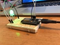
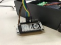
| − | I wanted to see if the TkkrLab hackerspace is open on my clock. For this I used an nodeMCU with a RGB led to request the spaceapi every 10 mins and display open (green) or | + | I wanted to see if the TkkrLab hackerspace is open on my clock. For this I used an nodeMCU with a RGB led to request the spaceapi every 10 mins and display open (green) or closed (red) status. The nodeMCU is a developer board with an ESP8266 / ESP12-E chip. There are a few different types of nodemcu's, check out this article for [https://frightanic.com/iot/comparison-of-esp8266-nodemcu-development-boards/ more information about these] |
| + | |||
| + | <gallery> | ||
| + | File:Nodemcu spacestate breadboard.JPG | ||
| + | File:Nodemcu spacestate LED connections.JPG | ||
| + | File:Nodemcu spacestate connections.JPG | ||
| + | File:Nodemcu spacestate led in clock.JPG | ||
| + | </gallery> | ||
=Resources= | =Resources= | ||
==Parts List== | ==Parts List== | ||
| − | * Clock | + | * [https://www.aliexpress.com/store/product/Free-Shippig-designer-artistic-wall-clock-runaway-clock-wall-clocks-with-day-and-date/910542_539870750.html Clock] |
| − | * nodeMCU v2 | + | * [http://www.dx.com/p/esp8266-esp-12e-development-board-serial-wi-fi-module-for-nodemcu-441215?Utm_rid=92935131&Utm_source=affiliate nodeMCU v2] |
| − | * 10 mm RGB LED | + | * [https://www.adafruit.com/products/848 diffuse 10 mm RGB LED] |
| − | * 1x 1K resistor | + | * 1x 1K resistor (you can alter this depending how brite the LED should be) |
| + | |||
| + | ==Software== | ||
| + | * source code for nodeMCU : https://github.com/zeno4ever/spacestatus_ESP | ||
| + | * Library for json processing https://bblanchon.github.io/ArduinoJson/ | ||
| + | * [https://www.arduino.cc/en/Main/Software Arduino IDE] for uploading source to nodeMCU | ||
| + | |||
| + | =Steps= | ||
| + | |||
| + | [[File:spacestatus_schematic.png|600px]] | ||
| + | |||
| + | |||
| + | I used male breadboard connectors to connect everything to the nodeMCU, you can solder the RGB led directly on the wire (with one resistor on the anode (+)) | ||
| + | |||
| + | The clock I have has a 6v that is connected to the Vin and GND of the nodeMCU | ||
| + | |||
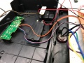
| + | * Check the clock you want to use if there is enough space inside to put nodeMCU inside and where to place the LED. | ||
| + | * Check if you can use the power of the clock and this is good for Vin. In my case i had 6 V, this in within the range of 4.5V ~ 9V. If you have a other version of nodeMCU check the documentation. | ||
| + | * Download the source and change the settings for your hackerspace. | ||
| + | * Upload code to nodeMCU via USB | ||
| + | * Connect the RGB LED and power in the the nodeMCU | ||
| + | |||
| + | |||
| + | ===LED remarks=== | ||
| + | If you order a LED chip check what type you buy, you have commen anode and commen cathode types. These have to be connected different I used an common anode. I include setting you can change. I have no tested this part so there may more changes needed to make this work. | ||
| + | |||
| + | I also use one resistor since i only show one color all times. If you want to use more then one color at a time then you should use a resistor per color, so 3 for R,G,B. | ||
| − | + | You can cut a part of the LED as long you don't touch the parts where the electronics are. For me I 'decapped' the LED with a iron saw and sanding it down to have a flat surface. | |
Latest revision as of 18:24, 9 April 2017
| Project: SpaceState nodeMCU ESP8266 Clock | |
|---|---|
| | |
| Name | SpaceState nodeMCU ESP8266 Clock |
| Initiator | zeno4ever |
| Status | 100% |
| Skills | Basic Electronics, Arduino Software (C) |
| Summary | Show space open/close state with nodeMCU / ESP-12E / ESP8266 |
I wanted to see if the TkkrLab hackerspace is open on my clock. For this I used an nodeMCU with a RGB led to request the spaceapi every 10 mins and display open (green) or closed (red) status. The nodeMCU is a developer board with an ESP8266 / ESP12-E chip. There are a few different types of nodemcu's, check out this article for more information about these
Resources
Parts List
- Clock
- nodeMCU v2
- diffuse 10 mm RGB LED
- 1x 1K resistor (you can alter this depending how brite the LED should be)
Software
- source code for nodeMCU : https://github.com/zeno4ever/spacestatus_ESP
- Library for json processing https://bblanchon.github.io/ArduinoJson/
- Arduino IDE for uploading source to nodeMCU
Steps
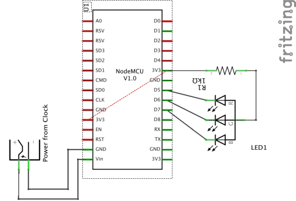
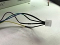
I used male breadboard connectors to connect everything to the nodeMCU, you can solder the RGB led directly on the wire (with one resistor on the anode (+))
The clock I have has a 6v that is connected to the Vin and GND of the nodeMCU
- Check the clock you want to use if there is enough space inside to put nodeMCU inside and where to place the LED.
- Check if you can use the power of the clock and this is good for Vin. In my case i had 6 V, this in within the range of 4.5V ~ 9V. If you have a other version of nodeMCU check the documentation.
- Download the source and change the settings for your hackerspace.
- Upload code to nodeMCU via USB
- Connect the RGB LED and power in the the nodeMCU
LED remarks
If you order a LED chip check what type you buy, you have commen anode and commen cathode types. These have to be connected different I used an common anode. I include setting you can change. I have no tested this part so there may more changes needed to make this work.
I also use one resistor since i only show one color all times. If you want to use more then one color at a time then you should use a resistor per color, so 3 for R,G,B.
You can cut a part of the LED as long you don't touch the parts where the electronics are. For me I 'decapped' the LED with a iron saw and sanding it down to have a flat surface.
