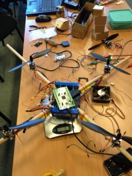
Quadcopter
From
| Project: Quadcopter | |
|---|---|

| |
| Name | Quadcopter |
| Initiator | Michielbrink en Vondel |
| Status | Unknown |
| Skills | lots of skills |
| Summary | awesome quadcopter with a lot of sensors |
The quadcopter
To give you an idea of what we are planning with our Quadcopter, here is a list of features we want to include:
- gyroscope
- accelerometer
- compass
- ultrasonic range sensors on every corner
- control via wifi
- live webcam stream
- according to a comment with the motors we bought: at 1,3Kg, speed up to 75km/h
- servo to tilt webcam.
- battery measurement through adc -> uart on msp430g2553.
- tm32f3 discovery board as brain.
- raspberry pi for the webcam stream and control of more fun stuff
- gps (in the distant future)
- and lots more!
de firmware voor de msp430g2553 (adc naar uart)
    #include <msp430.h>
    #include <stdbool.h>
    #include <stdio.h>

    #define GND         BIT4
    #define DAT         BIT5
    #define RXD		    BIT1
    #define TXD		    BIT2

    char buffer[4];
    int adc_new;
    int adc_old;
    char * adc_string;

    void uart_putc(unsigned char c);
    void uart_puts(const char *str);
    int adc_read();
    void Delay_ms(unsigned int ms);

    int main(void)
    {
        //msp430 init
        WDTCTL = WDTPW + WDTHOLD;         // Stop WDT
        BCSCTL1 = CALBC1_1MHZ;            // Set DCO to 1MHz
        DCOCTL = CALDCO_1MHZ;

        //pin init
        P1SEL  = RXD + TXD;
        P1SEL2 = RXD + TXD;
        P1DIR |= GND;
        P1OUT&=~GND;

        //uart init
        UCA0CTL1 |= UCSSEL_2;                     // SMCLK
        UCA0BR0 = 104;                            // 1MHz 9600
        UCA0BR1 = 0;                              // 1MHz 9600
        UCA0MCTL = UCBRS0;                        // Modulation UCBRSx = 1
        UCA0CTL1 &= ~UCSWRST;                     // Initialize USCI state machine
        IE2 |= UCA0RXIE;                          // Enable USCI_A0 RX interrupt

        //adc init
        ADC10CTL1 = INCH_5 + ADC10DIV_3 ;         // Channel 5, ADC10CLK/4
        ADC10CTL0 = SREF_0 + ADC10SHT_3 + ADC10ON + ADC10IE;  //Vcc & Vss as reference
        ADC10AE0 |= BIT5;                         //P1.4 ADC option

        __enable_interrupt();

        Delay_ms(1);                   // Wait for ADC Ref to settle

        while(1)
        {
            Delay_ms(500);
            adc_new = adc_read()*10/1023;
            if(adc_new != adc_old)
            {
                sprintf(adc_string, "%d",adc_new);
                uart_puts(adc_string);
                adc_old = adc_new;
            }
        }
    }

    //uart

    void uart_putc(unsigned char c)
    {
        while (!(IFG2&UCA0TXIFG));              // USCI_A0 TX buffer ready?
        UCA0TXBUF = c;                    		// TX
    }

    void uart_puts(const char *str)
    {
        while(*str) uart_putc(*str++);
    }

    //adc

    int adc_read()
    {
        ADC10CTL0 |= ENC + ADC10SC;             // Sampling and conversion start
        __bis_SR_register(CPUOFF + GIE);        // LPM0 with interrupts enabled
        return(ADC10MEM);
    }

    __attribute__((interrupt(ADC10_VECTOR)))
    void ADC10_ISR(void)
    {
      __bic_SR_register_on_exit(CPUOFF);        // Return to active mode
    }

    //delay

    void Delay_ms(unsigned int ms)
    {
        while(ms--)
        {
        __delay_cycles(1000);
        }
    }
