RGB shield
From
Parts used:
- 3x 1k ohm resistor
- 2x 5.6 ohm resistor (used for green and blue)
- 1x 12 ohm resistor (used for red)
- 3x BC547 transistor
- 1x RGB LED (http://dx.com/p/rgb-multicolored-led-light-bulbs-5-piece-pack-133084)
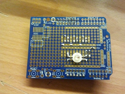
- 1x Arduino prototyping shield (http://dx.com/p/arduino-prototyping-shield-pcb-board-blue-138294)
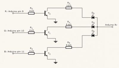
The RGB LED is connected to pins 9, 10 and 11 of the Arduino for red, green and blue;
Specifications for the RGB LED:
- R: Wavelength: 630~640nm / Brightness: 1000~1200MCD / Voltage: DC 1.8V~2.0V
- G: Wavelength: 515~525nm / Brightness: 3000~5000MCD / Voltage: DC 3.2V~3.4V
- B: Wavelength: 465~475nm / Brightness: 2000~3000MCD / Voltage: DC 3.2V~3.4V
- Rated current: 700~750mA
Because red needs a lower voltage, it uses the larger 12 ohm resistor.
All the parts are soldered on the bottom of the board (facing the Arduino) to prevent the parts from blocking the LED. Pin headers are added to connect the RGB shield to the Arduino.
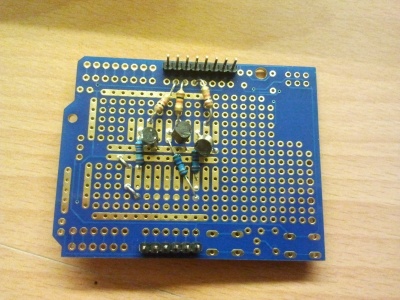
The RBG LED is the only part on the top side of the board - this way no parts will be blocking the light.