Tkkrduck
From
| Project: Tkkrduck | |
|---|---|
| |
| Name | Tkkrduck |
| Initiator | FriedZombie |
| Status | 100% finished |
| Skills | electronics |
| Summary | Tkkrduck, our new and lovely glow in the dark pet. |
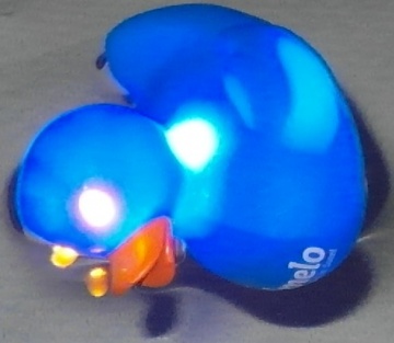
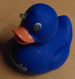
One day when it was hot outside a tiny swimming pool showed up at tkkrlab. Since we had a toy rubber ducky that was not too visible at night, I decided to hack it to make it more visible when it is in the pool with some nice LEDs.
It does look pretty cool as well, with those glowing yellow eyes.
Contents
Things needed
Components
- 1X 9V battery
- 1X rubber ducky
- 2X 5mm yellow LEDs
- 2X high brightness blue LEDs
- 2X NPN transistor or 1X Darlington transistor (I used 2X the BC338)
- thin electrical wire
- tin soldering wire
- superglue
- hotglue melt
- 1X 10K resistor
- 1X resistor for the two blue LEDs (in my case 68 Ohm)
- 1X resistor for the two yellow LEDs (in my case 180 Ohm)
for the correct values for the LEDs, you can use an online led calculator (choose: parallel leds)
Tools
- Soldering iron
- hotglue gun
- hand held drill
- 5mm drill bit
- wire stripper (or other means to strip wires)
- wire cutters
- exacto knife
- pricker
Construction
I didn't use a perfboard, since it are only a few components and it does save a little bit of space to solder the components to each other.
soldering
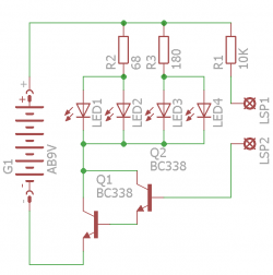
Solder the two LEDs together, Cathode to Cathode and Anode to Anode. Making sure that they are each pointing a different direction. (the cathode is the shorter leg, or it is the side with the notch on the LEDs).
If you didn't get a darlington transistor, you can make one the way I did. By soldering two resistors together the following way: Solder from both transistors the Collector together. After you have done that, solder the Emitter from one transistor to the Base of the other. This makes up a darlington transistor.
Cut about 5 cm of wire, strip both ends of it. Solder one end of it to the Emitter of the darlington transistor. Tin the other end of this piece of wire, this will be the ground wire.
Cut an other 5 cm of wire, strip both ends of it. Solder one end of it to the Base of the darlington transistor. Tin the other end of it. This will be one of the sense wires.
Cut of about 5cm of wire, strip both ends of it and solder the 3 resistors to one end of it and tin the other end. This will be the positive wire.
Cut an other 5cm length of wire, strip both ends of it and solder it to the 10k resistor. This will be the other sense wire.
Cut four lengths of wire that are longer then the height of the rubber ducky, the extra length of these wires will come in handy when fitting the eyes of the ducky. Solder two of them to the resistor meant for the yellow LEDs, and solder the other ends to the Anodes of the yellow LEDs (the Anode is the longer lead that is coming out of the led). Solder the two remaining wires you just cut to the (combined) Collector of the darlington transistor, together with the cathode leads from the blue LEDs. (the cathode is the shorter lead coming out of the led, or the side with the notch). Now solder the other end of these wires to the cathode side of the yellow LEDs.
Solder the Anode leads of the blue LEDs to the resistor meant for the blue LEDs.
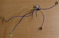
Hotgluing
Hotglue the circuit you just build together and make sure that the aren't any contacts where you didn't soldered them in the circuit. The hotmelt will hold it in place. Also make sure that you don't cover up the blue leds in a way that the light would be hindered.
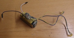
Now hotglue the whole thing onto the side of the 9V battery, making sure that the shape would still fit into the rubber ducky.
connecting the battery
Solder the positive wire of the circuit to the positive terminal of the battery and of course the negative wire to the negative terminal.
Now when you touch both sense leads with your finger, all the lights should turn on.
Operating on the duck
Take the drill and drill-bit and drill the 5mm holes for the yellow leds. After you have done that. take the exacto knife and cut a nice line on the under side of the rubber ducky. First fit in the yellow LEDs in the holes you just drilled, via the hole that was cut in the bottom of the duck. Fixate the leds with some superglue, you can just carefully drip it on the outside of the ducky.
Now fit in the rest of the contraption you just created inside the duck, and glue it in place with some hotglue.
Punch two holes in the underside of the duck and feed the sense wires trough, and bent them against the underside of the ducky. Glue them in place with some superglue. Make su`re that you don't cover up the bare tinned wires, otherwise it doesn't sense the water properly.
After everything is put inside the ducky, superglue the hole that was cut back together making sure that the seem is watertight.
Just drop a tiny bit of hotmelt in the hole in the middle of the duck, after the hotmelt has cooled of. coat it with a bit of superglue as well. This is to ensure to have a watertight seal of the duck, so that no water will seep in.
Release Tkkrduck
Tkkrduck is now ready to be released. Release it in it's natural habitat and it will really light up your evening or night.
