XBOX 360 RF Module
From
| Project: XBOX 360 RF Module (reverse engineering) | |
|---|---|
| 360x360px | |
| Name | XBOX 360 RF Module (reverse engineering) |
| Initiator | Peterbjornx |
| Status | {{{Status}}} |
| Skills | Programming, Reverse engineering, Electronics |
| Summary | Reverse engineering the XBOX360 rf/frontpanel module's control interface |
When I was repairing my XBOX 360 controller I needed a way to test it.
I remembered seeing a post about how the frontpanel/RF module of the XBOX360 had a USB interface and could be repurposed to connect wireless controllers to a PC, when I looked up this post it also mentioned a I2C-like interface for controlling the RF module (LED's, linking).
After some further research I found an article that gave some code to send commands over the interface and control some features, so I ported the code to the stellaris launchpad I use for prototyping and hacking. I immediately noticed that some commands were missing and as such I set out to discover the full protocol.
Hardware level
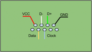
The module uses a custom connector with two rows of contacts, the top row provides a normal USB client interface while the bottom row contains connections for the control bus and power button.
Pinout:
| Pin | Description | Pin | Description |
|---|---|---|---|
| 1 | Vcc (3.3V) | 5 | Power button |
| 2 | USB D- | 6 | Control bus data |
| 3 | USB D+ | 7 | Control bus clock |
| 4 | Ground | 8 | Ground |
| 9 | NTX |
Control bus
The control bus is a weird one, clock is provided by the RF module but the XBOX360 initiates communication. The data line is open drain, as said before clock is driven by the module yet it is specified as BIDIR in the XBOX 360 mainboard schematics. I have not yet figured out how to receive data but sending data is pretty simple:
- Controller pulls DATA low to start communication.
- Controller waits for CLOCK to go low.
- Controller sets DATA to the current bit's value.
- Controller waits for CLOCK to go high.
- Repeat 2 to 4 for all 10 bits.
I hope to work out how to receive data.
USB
The USB interface is the same as that of the commercially available USB wireless controller dongle.
Its ID's are VID=045E PID=0291
Available drivers are those for the dongle mentioned above (to use them modify the INF to add the correct PID) and the linux xboxdrv drivers
Control bus protocol
The control bus appears to use 10bit commands where the first two bits are always 0, these commends are sent in big-endian (MSB first) bit-order.
Known commands and their names in my library:
| Data (bin) | Data (hex) | Name | Description |
|---|---|---|---|
| 00 0000 0100 | 0x004 | SYNC | Displays the XBOX 360 controller sync LED sequence (not sure if it really syncs) |
| 00 0000 1001 | 0x009 | CTRLR_OFF | Turns off all controllers |
| 00 0000 01RP | 0x01X | CONFIG | Configures the module (R bit is RF on/off, P bit is 0 for standing orientation) |
| 00 1000 0000 | 0x080 | LED_OFF | Turns off the LED controller |
| 00 1000 0100 | 0x084 | LED_INIT | Initializes the LEDs (needed before any other commands) and turns on the power LED |
| 00 1000 0101 | 0x085 | BOOTANIM | Same as LED_INIT + Displays the XBOX 360 boot LED sequence (appears to only work once) |
| 00 1000 1000 | 0x088 | LED_INIT_NOPWR | Initializes the LEDs (needed before any other commands) |
| 00 1000 1001 | 0x089 | BOOTANIM_NOPWR | Same as LED_INIT + Displays the XBOX 360 boot LED sequence (appears to only work once) |
| 00 1000 1100 | 0x088 | LED_INIT_BLPWR | Initializes the LEDs (needed before any other commands) and blinks the power LED |
| 00 1000 1101 | 0x089 | BOOTANIM_BLPWR | Same as LED_INIT + Displays the XBOX 360 boot LED sequence (appears to only work once) |
| 00 1010 ABCD | 0x0AX | SET_GREEN_LEDS | Sets the four green LEDs on or off (four least significant bits encode green led value) |
| 00 1011 ABCD | 0x0BX | SET_RED_LEDS | Sets the four red LEDs on or off (same as SET_GREEN_LEDS but independent of it) |
| 00 1100 0000 | 0x0C0 | CLEAR_ERROR | Clears any error display (blinking red leds or orange solid) |
| 00 1100 0001 | 0x0C1 | SLOW_BLINK_ALL | Blinks all four red LEDs |
| 00 1100 0001 | 0x0C2 | SLOW_BLINK_1 | Blinks top left red LED |
| 00 1100 0001 | 0x0C3 | SLOW_BLINK_2 | Blinks top right red LED |
| 00 1100 0001 | 0x0C4 | SLOW_BLINK_3 | Blinks bottom right red LED |
| 00 1100 0001 | 0x0C5 | SLOW_BLINK_4 | Blinks top left red LED |
| 00 1101 0000 | 0x0D0 | CLEAR_ERROR | Clears any error display (blinking red leds or orange solid) |
| 00 1101 0001 | 0x0D1 | FAST_BLINK_ALL | Blinks all four red LEDs |
| 00 1101 0001 | 0x0D2 | FAST_BLINK_1 | Blinks top left red LED |
| 00 1101 0001 | 0x0D3 | FAST_BLINK_2 | Blinks top right red LED |
| 00 1101 0001 | 0x0D4 | FAST_BLINK_3 | Blinks bottom right red LED |
| 00 1101 0001 | 0x0D5 | FAST_BLINK_4 | Blinks top left red LED |
| 00 1110 0000 | 0x0E0 | CLEAR_ERROR | Clears any error display (blinking red leds or orange solid) |
| 00 1110 0000 | 0x0E1_0x0EF | LED_AMBER | Sets all leds to amber colour |
There appears to be a priority in these commands: Blink overrides the values set by SET_GREEN and SET_RED leds, SET_GREEN and SET_RED override SYNC. When a command is being overridden it is still executed in background (E.g. you can set a value for the LEDs while they are blinking and once CLEAR_ERROR is sent, the value sent will be shown)
Example code
Here is the code i use to send the commands from my stellaris launchpad
void xbox_send_word(uint32_t word)
{
	uint32_t bit_ptr;
    	uint32_t edge_detect_buf;
    	/* Pull DATA low */
	ROM_GPIOPinTypeGPIOOutput(XBOX_BUS, XBOX_DATA);
    	ROM_GPIOPinWrite(XBOX_BUS, XBOX_DATA, 0);
	/* Send all the bits */
    	for (bit_ptr = XBOX_WORD_SIZE; bit_ptr >= 1; bit_ptr--){
    		/* Wait for clock to go low */
    		edge_detect_buf = XBOX_CLOCK;
    		while (edge_detect_buf == ROM_GPIOPinRead(XBOX_BUS, XBOX_CLOCK));
    		/* Set data to value */
    		ROM_GPIOPinWrite(XBOX_BUS, XBOX_DATA, ( word & (1 << (bit_ptr - 1)) ) ? XBOX_DATA : 0);
    		/* Wait for clock to go high */
    		edge_detect_buf = 0;
    		while (edge_detect_buf == ROM_GPIOPinRead(XBOX_BUS, XBOX_CLOCK));
    	}
    	/* Release DATA */
    	ROM_GPIOPinWrite(XBOX_BUS, XBOX_DATA, XBOX_DATA);
	ROM_GPIOPinTypeGPIOInput(XBOX_BUS, XBOX_DATA);

}
Credits
Writing the wiki page, porting, discovering BLINK_STOP: Peterbjornx
Pinout: Whoever leaked the XBOX360 schematics ;)
Pinout picture and most of the commands: [guy who writes this]
