TkkrLab lasercutter: Troubles and revelations with a lasercutter
TkkrLab laser cutter
Index
Intro
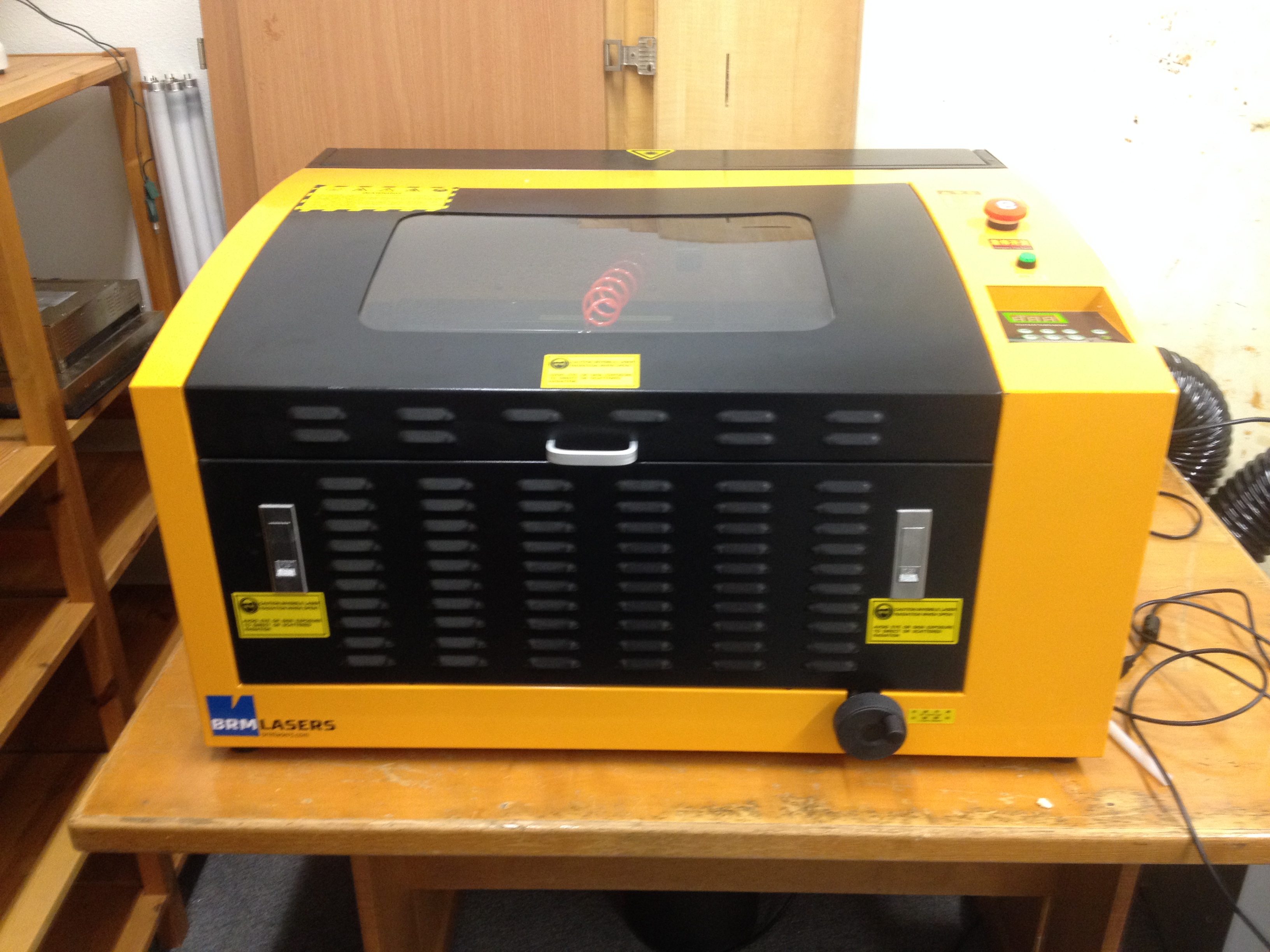
At some point TkkrLab invested in a lasercutter to make more projects possible, the choice fell on a CW3040 lasercutter. Although CW stands for Cowin the exact same model can be found made by other manufacturers as well, the only difference is the two letters in the beginning of the type.
The lasercutter came with a Lihuiyu Studio 6C6879-LASER-M2:6 DSP from 3wcad and was only compatible with coreldraw, it was usuable for rectangle shapes and engraving bitmaps. At had the most interesting issues with round shapes if they were not connected. So that wasn’t too usuable. So we opted for a smoothie clone board and replaced the DSP with that.
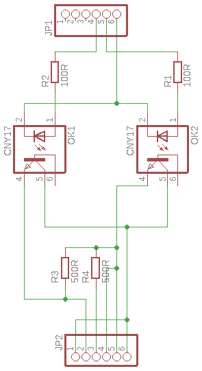
After some time running with the smoothie clone board clone, the lasertube gave out and took the powersupply with it. We replaced the lasertube for a “60 watt” 50 watt tube and a new power supply. To connect the new power supply, a opto board was created. But the tube didn’t get the full current it needed yet.
Although after some tweaking the power supply that was fixed as well.
Also to accomodate for the larget length tube, we added an extension cover to the right side of the laser cutter as well.
Because so much about the lasercutter has changed, I would call it the TK3040 or just the TkkrLab lasercutter.
Laser cutting
Basic technical information
To turn on the lasercutter, make sure that the red power button in the back is turned on and the emergency stop is pulled up. Before starting a lasercutter job make sure that the water cooling is running and the tiny compressor is blowing are trough the laserhead.
The TkkrLab lasercutter has a smoothieboard installed because the original DSP was not very usuable, but only worked well with engraving.
The working area on the laserbed is 400x300 mm, the cutting depth has a maximum of 15mm of material although in practice 6mm is more doable. Travel speed has a max of 8000 mm/sec with an acceleration of 300 mm/sec for both engraving and cutting.
The lasertube that currently is installed can do a initial burst of 60 watts (also operating the tube higher then 50 watt it will greatly reduce the lifetime of the tube), dropping of fast to 50 watt. This is normal behaviour, because it is technically a 50 watt tube.
To raise and lower the cutting bed, use the turn wheel on the right side of the lasercutter. clockwise to raise it counterclockwise to lower it.
The current firmware on the smoothieboard clone, is the stock frimware with the following configuration: config.
Program interface options
There are many programs and ways to interface with the TkkrLab laser cutter, in all instances it boils down to it uses G-code.
The first way is to connect lasercutter software directly to the lasercutter, but this is the slowest way of communication. This can be done via a telnet like connection. One of the biggest drawback of this is that, if a command string is send to the lasercutter it executes the command. After it successfully did it’s movement it sends back an ack to say to the software it has been done successfully. After wich the software sends an other line of G-code. The end result of this is that the lasercutter runs slower over all and the movement is a lot more jerky because of the starting and stopping of movement all the time.
The other way is to upload a G-code file directly to the lasercutter either directly via the program to the url in our case: http://lasercutter.tkkrlab.space/upload or upload a G-code file via http://lasercutter.tkkrlab.space
The lasercutter uses standard G-Code of course ignore the 3d printer specific ones. Although the TkkrLab laser cutter is based on a smoothieboard clone, that istelf is derivative of the grbl project Meaning that the documentation regarding the working is the same. The main benifit of the smoothieboard that the cpu is faster and has almost all the supporting hardware already on the board.
Visicut to send a job
The easiest way to prepare and send a job to the tkkrlab lasercutter is visicut, of course other programs are possible as well.
The first time after you installed visicut, it prompts you to choose wich default settings should be loaded. Simply choose “Netherlands, Enschede: TkkrLab” this loads the recommended default settings for the lasercutter. If you want to reset and get the recommended prompt again, simply choose “download recommended settings” from the “options” menu Also it is recommended to read the visicut manual for operation as well
Inkscape to prepare a job
To prepare a job, inkscape can be used to create an svg vector image. Of course any other program that can generate svg files can be used as well. But they all have their own bugs and quirks though. If you use inkscape, visicut has the option to install the visicut plugin. This makes it easier to import jobs from inkscape into visicut. This plugin will show up under “lasercut path” within the extensions menu in inkscape. the two options are: “add to visicut” and “open in visicut”. Add to visicut adds the vector drawing to visicut, keeping any old jobs on the plate as well. Open in visicut disgards the old job and starts a new one on an empty plate. Note if you have a selection within inkscape, that is send instead of the whole drawing.
To install the plugin, start visicut and choose “install inkscape plugin” under the “extras” menu.
If you want to engrave an image you can simply load an image into your drawing that isn’t a vector, this gets picked up by visicut to rasterize and create g-code for it. Also it doesn’t have to be black and white. (although it would be prefered to better guestimate the outcome of the job.
For otherr opterations you can use different line colors to engrave and cut, the default is cut for red and mark for blue. These colors can be changed under the advanced mapping within visicut. a black line or fill color is used for engraving as well.
Maintenance
Lens cleaning
To get access to the mirror, first remove the beam expander from the laserhead, this is the piece at the bottom of the laserhead. To release it remove the screws at either side. After the beam expander is removed, unscrew the lens holder. This is the part where the beam expander was clamped onto.
Carefully tip out the lens on some microfibre cloth or something that will not scratch up the surface of the lens, these things do scratch easily!
First blow of any dust that has settled on the lens with a blowout bulb or something else gentle. After this is done any stuff that remeans on the lens, use some cotton swabs or balls with some acetone to clean of the remainder. If the acetone streaks, you probably moved too fast with the cotton ball or swab. Also clean by moving in concentric circles. To remove grease or fingerprints you can use distilled white vinegar or of course some other mild acidic substance. Don’t clean it for more then 30 secconds. Ohterwise it could start to effect the surface. Becaise it doesn’t evaporate quickly, clean directly afterwards with some acetone. Sometimes you hear for things like this some coke beverage should be used, but that is definately not recommended. It is true that coke is acidic, but has alot more additives as well. I blame the internet for this misconception of coke being a miracle cleaning product.
To remount the lens, drop the lens carefully in the lens holder. Make sure that the flat or hollow side of the lens is facing up. Screw back the lensholder to the laserhead. Reattach the beam expander to the lens holder, and screw back in the screws taken out earlier, just hand tight. Don’t overtighten them, otherwise the thread will be stripped out easily.
Mirror cleaning
In spite of some beliefs that optics never should be cleaned on a laser cutter, but this is necessary for sure. (1, 2, 3) There are three mirrors in total in the laser cutter, one of them in the top of the laserhead. The mirror in the laserhead is the only one that can not be cleaned without removing it completely, but this mirror doesn’t have to be cleaned that often since the angle it is in. Most times you can clean the mirrors within the mirror mounts without removing them, if there isn’t too much filth buildup on top of them. To clean the mirror, dab or spray a cotton swab or ball with some acetone and gently roll it over the surface of the mirror. Do not force or rub it, because the mirror is easily scratched. After this inspect if there is any residue left on the mirror. If you clean the mirror while still being installed, don’t use any distilled white vinegar or anything else acidic on them, since it gets trapped within the mirror mount.
In the case there is still residue left on the mirror and it isn’t possible to clean them properly or if there is some grease you have to remove them to be able to clean them better. To release the mirror from it’s mount, turn the retention ring anticlockwise while holding the mirror manifold to make sure not to twist the stand in half popping the springs out. Although it is possible to put the springs back in place, it is a pain in the neck to do so. To remove the mirror from the laserhead simply unscrew the retention clip, with a philips screw driver and carefully lift out the mirror.
After the mirror has been removed, you can clean them the same way as the lens.
To reinstall the mirror, place the mirror back into the manifold of the mirror stand and carefully screw on the retention ring hand tight clockwise. Make sure not to bump out the mirror whole doing so. To reseat the mirror in the laserhead, drop it back into place carefully and reattach the retention clip with the philips crewdriver.
Mirror calibration
within the laser cutter there are 3 mirrors, reflecting the laser beam from the lasertube in the back towards the laser head down to the cutting surface. Mirror #1 is located directly in front of the laser tube, mirror #2 is located on the left on the x beam gliding along with the y movement. Mirror #3 is located within the top of the laserhead and is the only one that is not adjustable.
C02 laser tubes produce infrared light, that means it is not vissible to the naked eye and cant really be used to align the mirrors without a different aid. Within the more expensive lasercutters there is a visible low power laser source available. This visible laser beam is then injected with a beam combiner. But since the beam combiners are for some unexplained reason rather expensive we have to calibrate the lasercutter without this nice visible aid.
To calibrate a lasercutter without a visible laser source, often people use masking tape or thin paper to stick on mirror #2 and on the entrance of the laserhead. This might seem like a good idea, because it is easy and fast to set up. Also some deviation from the center introduced is fine, as long as the diviation is the same at all 4 corners of the cutting area and is no more out of the center by about 2mm. If the deviation is too great the laserbeam will bounce within the laserhead creating a ghosting effect on the material that is being cut. The deviation must be the same in all 4 corners. The reason for this is, it will influence the cutting power of the lasercutter. What a better solution would be is to use thin piece plywood or cardboard with double sided tape. There are some ready made templates to cut the pieces of ply or cardboard. Make sure that for mirror mounts the material isn’t too thick since they are at a 45 degree angle, the deviation introduced is the thickness of the material that is used as an aid on the mirror. Also carefully remove the alignment aids carefully, since the mirror mounts are spring loaded. The mirror mounts have three screws on the back of them, to adjust the alignment of the mirror.
To short fire the tube, unplug the laser power supply control connector. This way the test button becomes usuable to short fire the tube, however this can also be done with some G-code.
The first thing that has to be aligned has to be the tube itself, this only has to be done only once after the tube is replaced. When mounting the tube, there are some pieces of rubber to cushion the tube within the pipe clamps, these can be fenagled around a bit. Softly press the round piece of carboard or ply on the mirror mount #1 and turn on the tube for a short time and adjust the tube alignment until it hits the center of the mirror. Don’t forget to carefully remove the alignment aid from the mirror mount.
Aligning mirror #1: Softly press the round piece of carboard or ply on the mirror mount #2 and turn on the tube for a short time and adjust the alignment of mirror #1 until it hits the center of mirror #2. Don’t forget to carefully remove the alignment aid from the mirror mount.
Aligning mirror #2: Softly press the rectangle piece of cardboard or ply on the laserhead. Make sure the the target is over the hole in the leaserhead. Place the rectangle piece directly against the flat surfaces of the laserhead, this way the target is centered. Turn on the tube for a short time and adjustthe alignment of mirror #2 until it hits the target on the right spot. Make sure that the alignment is the same in the 4 corners of the cutting area. If the alignment drifts too much. It can be that the first two mirrors are slightly out of alignment. Don’t forget to remove the alignment aid from the laserhead.
Lubrication
To reduce wear and tear on the moving parts, it is important to keep the x and y rods lubricated. There are two Y beams and one X beam, over the X beam the lasercutter cariage movers left and right. The y beams are on either side of the cutting bed. Use some sewing machine oil to grease them while making sure not to get grease on the mirrors. Also don’t overdo it either, otherwise it could drip on working peaces while cutting.
Cut perimeter
To mark the exact cutting area, you can tape of the sides and use the cut-perimeter.gcode to cut out the exact dimesnions of the erea. Maybe in the feature we could install some steal rulers, but at this time it hasn’t been missed yet.
Replacement parts
Laser mirror (reflective round thing)
The TkkrLab laser cutter will take mirrors with a diameter of 20mm and a thickness of 3mm. (This stated 25mm before, which is wrong.) Base materials can either be Si Mo or Cu, the differences are described below. Currently installed are Si type mirrors. The current mirror set that is installed into the laser cutter is Si, however more recommended with novice use would Mo since they are more scratch and heat resistant.
K9 Gold coated K9(BK7) crystal glass (borosilicate crown glass). They are far from ideal. when using them with a laser beam. They are of poor quality and can only be used with laser system of 35 watts and below. At least they are cheap Refractive index: n = 17.768
Si Gold coated silicon glass, these mirrors have a good reflective index. They should be replaced about once a year and are usable for up to 60 watts laser systems. Refractive index: n = 17.768
Mo Mirror made out of molybdenum, it does not have the best reflective index, but they are tough and rather scratch resistant. Also they are ideal for high power laser cutters 80 watts and up. Refractive index: n = 13.478
Cu gold coated copper mirror, these mirrors have a good reflective index but stronger than Si. They don’t have to be replaced often. Ideal for higher power laser cutters 50 watts and up Refractive index: n = 17.768
Laser lens (the thing that focuses the beam, this is not reflective)
The TkkrLab laser cutter will take a lens with a diameter of 12mm and a thickness between 2 and 3mm. The material has to be ZnSe since normal glass and other materials will not allow infrared to pass trough. We currently have a focal length (fl) of 50.8mm, this is also recommended for an allround machine.
The most common focal lengths are 38.1mm 50.8mm 63.5mm 76.2mm and 101.6mm The longer the focal length is the narrower the beam is, meaning that you can cut trough thicker material. The shorter focal length has the benefit to be much better with engraving and cutting trough thin materials, while the longer focal length is better for cutting thick materials. For a more all round machine the 50.8mm is recommended.
Laser tube
The TkkrLab laser cutter has a 50 watt sealed CO2 laser tube installed with an expected life of 3000 to 4500 hours of operation. Within the laser tube because it is a sealed version is a complex mixture of different gasses. The lifetime of the tube is also really depended on the mixture used. It is possible to produce a higher wattage output then the tube is rated for, simply by allowing more current to flow trough. But this really shortens the lifespan of the part because the gasses inside the tube decompose much faster. Because this is possible some laser tube vendors have the habit of overselling the wattage because of this, be warned. The diameter does not have much effect on the laser strength, length does.
The length of a 50 watt tube is 1000mm. Operational current is 22ma. Ignition voltage is 24KV and operation voltage is 16KV. It is fine if the voltage is higher as long as the current isn’t exceeded. The tube can be over driven to 60 watts but that is not recommended.
Propper cooling is also very important for the co2 laser tube, overheating will decompose the gasses inside pretty fast.