Led sign board
From
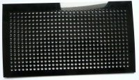
At the Eth0 winter edition the FabLab truck was there and i had a chance to use the lasercutter. There was some scrap black pexiglass and i thought it would be nice to make a led sign board so i let the lasercutter cut 512 holes (16 x 32) of 5mm out of the pexiglass. Actualy i wanted 16x64 but since that did not fit on the available material i now have 2 pieces of 16x32 holes.
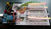
To control all those leds i currently have a breadboard test setup with an arduino, a led driver IC (CAT 4016W-T1, 16 channel constant current sink driver), a line driver IC (74HC138, 3 to 8 line decoder) and some misc. parts together with 4 rows of 16 bi-color leds. The line driver is used to scan all the rows (4 rows of green and 4 rows of red) at an interval of 8 microseconds. 128 of these intervals are used to control the brightness of the row in 128 Steps (Soft PWM). For 8 rows the total scan time will be 8us * 128 * 8rows=8,192 milliseconds or about 122Hz. This is fast enough for a non flickering display. The led driver IC is connected to the hardware SPI interface. To connect 32 rows of of 16 leds from 1 board i'll use 8 led driver chips.
In the mean time the parts have arrived but I'm a little busy with other projects so finishing this will take some more time.
